Login

We are experiencing technical difficulties. Your form submission has not been successful. Please accept our apologies and try again later. Details: [details]

Download

Register

We are experiencing technical difficulties. Your form submission has not been successful. Please accept our apologies and try again later. Details: [details]

Download

Thank you for registering

An email to complete your account has been sent to

Return to the website

get direct access

Fill in your details below and get direct access to content on this page

Text error notification

Text error notification

Checkbox error notification

Checkbox error notification

We are experiencing technical difficulties. Your form submission has not been successful. Please accept our apologies and try again later. Details: [details]

Download

Thank you for your interest

You now have access to G7S

A confirmation email has been sent to

Continue to page

Please or get direct access to download this document

G7S

G7S

Relays with forcibly guided contacts

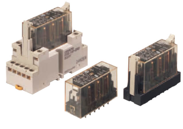
The slim G7S-_-E relay family with forcibly guided contacts is available as a six-pole type in two different contact combinations. Terminals are arranged for easy PCB layout. It can be soldered directly to a PCB or used together with the P7SA sockets.

  • Forcibly guided contacts
  • Conforms to EN 50205
  • NO contacts: 10 A at 250 VAC and 10 A at 30 VDC, NC contacts: 6 A at 250 VAC and 6 A at 30 VDC (for resistive loads)
  • Reinforced insulation between inputs and outputs and poles
  • 4- and 6-pole relays available

Specifications & ordering info

Ordering information

Relays with forcibly guided contacts

Type

Sealing

Poles

Contacts

Rated voltage

Order code

Standard

Flux-tight

6 poles

4PST-NO, DPST-NC

24 VDC

G7S-4A2B-E

3PST-NO, 3PST-NC

G7S-3A3B-E

Sockets

Type

LED indicator

Rated voltage

Order code

Track-mounting

Track mounting and screw mounting
possible

Yes

24 VDC

P7S-14F-END

Back-mounting

PCB terminals

No

-

P7S-14P-E

Specifications

Ratings

Coil

Rated voltage

Rated current (mA)1

Coil resistance (Ω)1

Max. voltage (V)2

Power consumption (W)

24 VDC

30

800

110%

Approx. 0.8

Contacts

Item

Resistive load

Rated load

NO contact

10 A at 250 VAC, 10 A at 30 VDC

NC contact

6 A at 250 VAC, 6 A at 30 VDC

Rated carry current

NO contact

10 A

NC contact

6 A


Item

Resistive load

Maximum switching voltage

250 VAC, 30 VDC

Maximum switching current

NO contact

10 A

NC contact

6 A

G7S-_-E Characteristics of Sockets

Model

P7S-14F-END

P7S-14P-E

Continuous current

10 A

Dielectric strength

2000 VAC for 1 min. between terminals

Insulation resistance

1000 MΩ min. 3

Ambient operating humidity

25 to 85%

5 to 85%

Characteristics

Contact resistance4

100 mΩ max.

Operating time5

50 ms max.

Release time2

50 ms max.

Maximum operating frequency

Mechanical

18,000 operations/h

Rated load

1,800 operations/h

Insulation resistance

100 MΩ min.

Durability6

Mechanical

10,000,000 operations min. (at approx. 18,000 operations/h)

Electrical

100,000 operations min. (at the rated load and approx. 1,800 operations/h)

Inductive load switching capability7 (IEC60947-5-1)

NO Contact

AC15 AC240V 5A, DC13 DC24V 2A

NC Contact

AC15 AC240V 3A, DC13 DC24V 2A

Ambient operating temperature

-25 to 70°C (with no icing or condensation)

Ambient operating humidity

5% to 85%

Note: The values listed above are initial values.


Please check Omron in the Internet for updated information on product reliability data and the SISTEMA libraries: http://industrial.omron.eu/safety


1. The rated current and coil resistance are measured at a coil temperature of 23°C with tolerances of ±15%.

2. The maximum voltage is based on an ambient operating temperature of 23°C maximum.

3. Measurement conditions: Measurement of the same points as for the dielectric strength at 500 VDC.

4. Measurement conditions: 5 VDC, 10 mA, voltage drop method.

5. Measurement conditions: Rated voltage operation, ambient operating temperature: 23°C, contact bounce time is not included.

6. The durability is for an ambient temperature of 15 to 35°C and an ambient humidity of 25% to 75%.

7. AC15: cos φ = 0.3, DC13: L/R = 96-ms

How can we help you?

If you have a question or would like to ask for a quote, please contact us or send a request.

+44 (0)870 752 0861
Contact us

Contact me G7S

g7s- -e temp prod

Please, complete all the fields marked with *. Your personal details will be handled confidentially.

Text error notification

Text error notification

Text error notification

Text error notification

Text error notification

Country error notification

Details

Text area error notification

Checkbox error notification

Checkbox error notification

Thank you for submitting your request. We will come back to you as soon as possible.

We are experiencing technical difficulties. Your form submission has not been successful. Please accept our apologies and try again later. Details: [details]

Download
+44 (0)870 752 0861
+44 (0)870 752 0861
Request quotation
Request quotation

Quotation for G7S

By completing this form you can request a quotation. Your personal details will be handled confidentially.
g7s- -e temp prod

Personal details

G7S

Text error notification

Text error notification

Text error notification

Text error notification

Text error notification

Country error notification

Quote details

Select notification error

Select notification error

Text area error notification

Checkbox error notification

Checkbox error notification

Thank you for requesting a quotation. We will provide you with the required information as soon as possible.

We are experiencing technical difficulties. Your form submission has not been successful. Please accept our apologies and try again later. Details: [details]

Download
Request quotation
Request quotation

Downloads