G6D4
G6D4
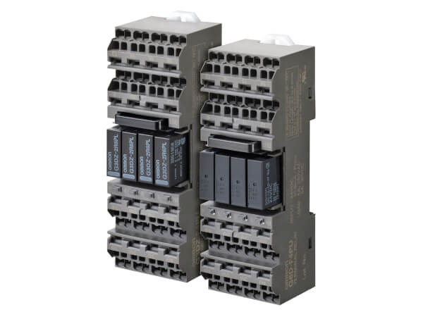
Model with Push-In Plus technology Added to Terminal Relays with Four-point Output Lineup
- Realized 5 A rating by optimal designs for wide variety of applications (Push-In Plus technology).
- Push-In Plus terminal enables work reduction and requires no retightening.
- Short Bars (order separately) ensure easy common wiring and crossover wiring to adjacent terminal relays.
- Double wire method enables branch wiring (Push-In Plus technology)
- Each relay has independent coils and contacts for PLC output compatible (both NPN and PNP).
- Mechanical Relay models and power MOS FET relay models (for high frequency contact ratings) are available.
- LED operation indicator, diode for coil surge absorption, and tools for easy removal of relays are included as standard equipment.
- UL and CSA certification for standard models. VDE certification for Screws terminal, TÜV certification for Push-In Plus terminal. IP20 protection code for Push-In Plus models."
Specifications & ordering info
Ordering information
Relays
| Terminal | Mounted Relay type | Contact form | Operation coil ratings | Order code
2
When your order, specify the
rated voltage. |
|---|---|---|---|---|
| Push-In Plus technology | Mechanical Relay | SPST x 4 (1NO x 4) |
12 VDC | G6D-F4PU |
| 24 VDC | ||||
| Power MOS FET relay | 12 VDC | G3DZ-F4PU | ||
| 24 VDC |
Accessories (Order Separately)
Connection socket (single sales available)
| Applicable model | Operation coil ratings | Order code
2
When your order, specify the
rated voltage. |
|---|---|---|
| G6D-F4PU/G3DZ-F4PU (Model with Push-In Plus technology) |
12 VDC | P6DF-F4PU |
| 24 VDC |
Single socket which does not mount a relay (with cover).
Short Bar (G6D-F4PU/G3DZ-F4PU (Model with Push-In Plus technology))
| Pitch | Applicable models | Number of poles | Color | Order code
2
Replace the box ( |
|---|---|---|---|---|
| 7.75 mm | G6D-F4PU G3DZ-F4PU P6DF-F4PU |
2 | Red (R) Blue (S) Yellow (Y) |
PYDN-7.75-020 |
| 3 | PYDN-7.75-030 |
|||
| 4 | PYDN-7.75-040 |
|||
| 20 | PYDN-7.75-200 |
Use the Short Bars for crossover wiring within one Socket or between Sockets.
Replacement Relay (G6D-F4PU/G3DZ-F4PU (Model with Push-In Plus technology))
| Applicable Terminal Relay Model | Operation coil ratings | Order code
2
When your order, specify the
rated voltage. |
|---|---|---|
| G6D-F4PU | 12 VDC | G6D-1A-ASI |
| 24 VDC | ||
| G3DZ-F4PU | 12 VDC | G3DZ-2R6PL |
| 24 VDC |
Parts for DIN Track Mounting
| Appearance | Type | Order code | |
|---|---|---|---|
 |
DIN Tracks | 1 m | PFP-100N |
| 0.5 m | PFP-50N | ||
 |
End Plate
2
When mounting support
rail, please use End Plate (Model PFP-M). |
PFP-M | |
 |
Spacer | PFP-S | |
Specifications
G6D Mechanical Relay
Coil ratings
| Operation coil rating | Rated current (mA) |
Coil resistance (Ω) |
Must operate voltage (V) |
Must release voltage (V) |
Max. voltage (V) |
Power consumption (mW) |
|
|---|---|---|---|---|---|---|---|
| DC | 12 | 18.7 | 720 | 70% max.
2
The must operate
voltage is 75% or less of the rated voltage if the relay is mounted
in the upside down. |
10% min. | 130% | Approx. 200 |
| 24 | 10.5 | 2,880 | |||||
- Rated current and coil resistance were measured at a coil temperature of 23°C with a tolerance of ±20%.
- Performance characteristic data are measured at a coil temperature of 23°C.
- The maximum allowable voltage is the maximum value of the operating voltage for the relay coil operating power supply. There is no continuous allowance.
- The rated current includes the terminal’s LED current.
Contact ratings
| Model | G6D-F4PU (Model with Push-In Plus technology) |
|---|---|
| Load | Resistive load (cos φ = 1) |
| Rated load | 5 A at 250 VAC, 5 A at 30 VDC |
| Rated carry current | 5 A |
| Max. switching voltage | 250 VAC, 30 VDC |
| Max. switching current | 5 A |
| Max. switching capacity (reference value) |
1,250 VA, 150 W |
Characteristics
| Model | G6D-F4PU (Model with Push-In Plus technology) |
|
|---|---|---|
| Item | Relay output | |
| Contact resistance
2
Measurement
condition: 1 A at 5 VDC |
100 mΩ max. | |
| Operate time
2
Ambient temperature condition: 23°C |
10 ms max. | |
| Release time
2
Ambient temperature condition: 23°C |
10 ms max. | |
| Insulation resistance | 1,000 MΩ min. (at 500 VDC) | |
| Dielectric strength |
Between coil and contacts |
2,000 VAC, 50/60 Hz for 1 min |
| Between contacts of the same polarity |
750 VAC, 50/60 Hz for 1 min | |
| Shock resistance voltage (between coil and contacts) |
4,000 V (1.2 × 50 μs) | |
| Vibration resistance |
Destruction | 10 to 55 to 10 Hz, 0.75-mm single amplitude (1.5-mm double amplitude) |
| Malfunction | 10 to 55 to 10 Hz, 0.75-mm single amplitude (1.5-mm double amplitude) |
|
| Shock resistance |
Destruction | 500 m/s2 |
| Malfunction | 100 m/s2 | |
| Endurance | Mechanical | 20,000,000 operations min. (switching frequency: 18,000 operations/hr) |
| Electrical
2
Ambient temperature condition: 23°C |
70,000 operations min. (5 A at 250 VAC, resistive load)70,000 operations min. (5 A at 30 VDC, resistive load)(at 1,800 switching frequencies/hr) |
|
| Failure rate P Level (reference value
2 )This value is measured at 120 switching frequencies/min. |
10 mA at 5 VDC | |
| Ambient operating temperature, Ambient storage temperature |
–25 to 55°C (with no icing) | |
| Ambient operating humidity | 45% to 85% | |
| LED color | Yellow | |
| Sealing | IP20 | |
| Weight | Approx. 95 g | |
G3DZ Power MOS FET Relay Specifications
Input (per G3DZ Power MOS FET Relay)
| Rated voltage | Operating voltage | Must operate voltage level |
Must release voltage level |
Input impedance | Rated current | |
|---|---|---|---|---|---|---|
| DC | 12 | 9.6 to 14.4 VDC | 9.6 VDC max. | 1 VDC min. | 2 kΩ ±20% | 8.0 mA ±20% |
| 24 | 19.2 to 28.8 VDC | 19.2 VDC max. | 4 kΩ ±20% | 8.2 mA ±20% | ||
The rated current includes the terminal’s LED current.
Output (per G3DZ Power MOS FET Relay)
| Rated operating voltage | Load voltage range | Load current | Inrush current resistance |
|---|---|---|---|
|
5 to 240 VAC 5 to 100 VDC |
3 to 264 VAC 3 to 125 VDC |
100 μ to 0.3 A | 6 A (10 ms) |
There is no output polarity for the G3DZ.
Characteristics
| Model | G3DZ-F4PU (Model with Push-In Plus technology) |
|---|---|
| Item | Power MOS FET relay output |
| Must operate time | 10 ms max. |
| Release time | 15 ms max. |
| Output ON-resistance | 2.4 Ω max. |
| Leakage current at OFF state | 10 μA max. (at 125 VDC) |
| Insulation resistance | 100 MΩ min. (at 500 VDC) |
| Dielectric strength between I/O | 2,000 VAC, 50/60 Hz for 1 min |
| Vibration resistance | 10 to 55 to 10 Hz, 0.75-mm single amplitude (1.5-mm double amplitude) |
| Shock resistance | 500 m/s2 |
| Ambient operating temperature, Ambient storage temperature |
–25 to 55°C (with no icing) |
| Ambient operating humidity | 45% to 85% |
| LED color | Yellow |
| Sealing | IP20 |
| Weight | Approx. 95 g |
Need assistance?
We’re here to help! Reach out, and our specialists will assist you in finding the best solution for your business.
Contact me G6D4

Thank you for submitting your request. We will come back to you as soon as possible.
We are experiencing technical difficulties. Your form submission has not been successful. Please accept our apologies and try again later. Details: [details]
DownloadQuotation for G6D4
By completing this form you can request a quotation. Your personal details will be handled confidentially.

Thank you for requesting a quotation. We will provide you with the required information as soon as possible.
We are experiencing technical difficulties. Your form submission has not been successful. Please accept our apologies and try again later. Details: [details]
Download
