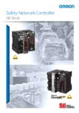
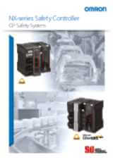
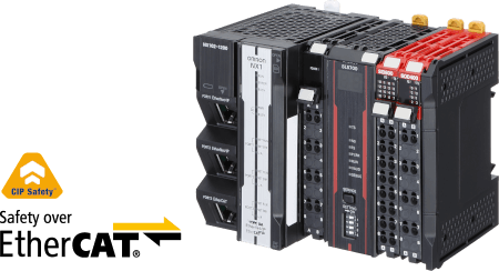
CIP Safety
From a production line to a single machine safety solution
Quick, easy, and flexible to integrate safety into production lines
- 1 built-in EtherNet/IP port (100Base-TX)
- 2 built-in CIP-Safety on EtherNet/IP ports
- Up to 254 safety connections with NX-SL5700
- Up to 32 NX I/O Units per Communication Control Unit
- Multi-cast packet possible
- Possible hybrid solution combining NX1 controller with NX-SL5000 series
Specifications & ordering info
Ordering Information
NX-series Communication Gateway Unit
| Unit type | Appearance | Supported communications protocol | Number of communications connectors | Network variables | Unit version | Order code |
|---|---|---|---|---|---|---|
| Communication Control Unit |
 |
EtherNet/IP
2
Routing of the CIP Safety protocol
is supported. |
3 | 2
2
PORT1 is an independent port. PORT2A and
PORT2B are the ports with a built-in Ethernet switch. |
Ver. 1.01 | NX-CSG320 |
One NX-END02 End Cover is provided with the NX-CSG320 Communication Control Unit.
NX-series Safety Control Units
Safety CPU Units
| Unit type | Appearance | Specifications | Unit version | Order code | |||
|---|---|---|---|---|---|---|---|
| Maximum number of safety I/O points | Program capacity | Number of safety I/O connections | I/O refreshing method | ||||
| Safety CPU Unit (NX-SL5 |
 |
1024 points | 2048 KB | 128 | Free-Run refreshing | Ver. 1.3 | NX-SL5500 |
|
2032 points | 4096 KB | 254 | NX-SL5700 | |||
Refer to your local OMRON website for
details of the NX-SL5
Safety Input Units
| Unit type | Appearance | Specifications | Unit version | Order code | ||||||
|---|---|---|---|---|---|---|---|---|---|---|
| Number of safety input points |
Number of test output points |
Internal I/O common |
Rated input voltage |
OMRON special safety input devices |
Number of safety slave connections |
I/O refreshing method |
||||
| Safety Input Units |  |
4 points | 2 points | Sinking inputs (PNP) | 24 VDC | Cannot be connected.
2
Various OMRON special safety input devices can be connected directly without a special controller. For detail of connectable OMRON special safety input devices, refer to NX-series User's Manual Safety Control Unit/Communication Control Unit (Cat. No. Z395). |
1 | Free-Run refreshing | Ver. 1.1 | NX-SIH400 |
|
8 points | Cannot be connected. |
Ver. 1.0 | NX-SID800 | ||||||
Safety Output Units
| Unit type | Appearance | Specifications | Unit version | Order code | |||||
|---|---|---|---|---|---|---|---|---|---|
| Number of safety output points |
Internal I/O common |
Maximum load current | Rated voltage |
Number of safety slave connections |
I/O refreshing method |
||||
| Safety Output Units |  |
2 points | Sourcing outputs (PNP) |
2.0 A/point, 4.0 A/Unit at 40°C, and 2.5 A/Unit at 55°C The maximum load current depends on the installation orientation and ambient temperature. |
24 VDC | 1 | Free-Run refreshing | Ver. 1.0 | NX-SOH200 |
|
4 points | 0.5 A/point and 2.0 A/Unit | NX-SOD400 | ||||||
Automation Software Sysmac Studio
Please purchase a DVD and required number of licenses the first time you purchase the Sysmac Studio. DVDs and licenses are available individually. Each model of licenses does not include any DVD.
| Product name | Specifications | Number of licenses | Media | Order code |
|---|---|---|---|---|
| Sysmac Studio Safety Edition Ver. 1.
2
The Safety Edition can be used with the Communication Control Unit and EtherNet/IP Coupler Unit. |
Sysmac Studio Safety Edition is a license including necessary setting functions for the safety control system. Note:This
product is a license only. You need the Sysmac Studio Standard Edition
DVD media to install it.
|
1 license | – | SYSMAC-FE001L |
| Sysmac Studio Standard Edition Ver. 1.
2
The Sysmac Studio Standard Edition License (SYSMAC-SE2 |
The Sysmac Studio is the software that provides an integrated environment for setting, programming, debugging and maintenance of machine automation controllers including the NJ/NX-series CPU Units, NY-series Industrial PC, EtherCAT Slave, and the HMI. Sysmac Studio runs on the following OS. Windows 7(32-bit/64-bit version)/8(32-bit/64-bit version)/8.1(32-bit/64-bit version)/10(32-bit/64-bit version) |
– (Media only) | DVD | SYSMAC-SE200D |
For details of the Automation Software Sysmac Studio, refer to your local OMRON website.
Optional Products
| Product name | Specifications | Order code |
|---|---|---|
| Memory Card | SD memory card, 2 GB | HMC-SD291 |
| SD memory card, 4 GB | HMC-SD491 | |
| Unit/Terminal Block Coding Pins | For 10 Units (Terminal Block: 30 pins, Unit: 30 pins) | NX-AUX02 |
| Product name | Specifications | Order code | |||
|---|---|---|---|---|---|
| No. of terminals | Terminal number indications | Ground terminal mark | Terminal current capacity | ||
| Terminal Block | 8 | A/B | Provided | 10 A | NX-TBC082 |
| 8 | A/B | None | 10 A | NX-TBA082 | |
| 16 | A/B | None | 10 A | NX-TBA162 | |
Accessories
Communication Control Unit Accessories
| Product name | Remark | Order code |
|---|---|---|
| End Cover | One End Cover is provided with the Communication Control Unit. | NX-END02 |
Specifications
Regulations and Standards
NX-series Safety Control Units
| Certification body | Standards | |
|---|---|---|
| TÜV Rheinland
2
The FSoE protocol was certified for applications in which OMRON FSoE devices are connected to each other. For compatibility with FSoE devices other than OMRON FSoE devices, the customer must validate FSoE communications. |
EN ISO 13849-1EN ISO 13849-2IEC 61508 parts 1-7IEC/EN 62061IEC/EN 61131-2 | IEC 61326-3-1IEC 61131-6
2
Only
NX-SL5500/5700 have obtained IEC 61131-6 and FSPC certifications. |
| UL | NRAQ (UL61010-1, and UL 61010-2-201)NRAG
(ANSI/ISA 12.12.01, or UL 121201)NRAQ7 (CSA C22.2 No. 61010-1, and
CSA C22.2 No. 61010-2-201)FSPC (IEC 61508 and ISO 13849)
2
Only
NX-SL5500/5700 have obtained IEC 61131-6 and FSPC certifications. |
|
- Requirements for SIL 3 (Safety Integrity Level 3) in IEC 61508, IEC/EN 62061, (Functional Safety of Electrical/Electronic/Programmable Electronic Safety-related Systems)
- Requirements for PLe (Performance Level e) and for safety category 4 in EN ISO13849-1
The NX-series Safety Control Units are also registered for RCM, EAC, and KC compliance.
NX-series Communication Control Unit
| Certification body | Standards |
|---|---|
| UL | NRAQ (UL61010-1, and UL 61010-2-201)NRAG (UL 121201) |
The NX-series Communication Control Units are also registered for RCM, EAC, and KC compliance.
General Specifications
| Item | Specifications | |
|---|---|---|
| Enclosure | Mounted in a panel (open) | |
| Grounding method | Ground to 100 Ω or less | |
| Operating environment |
Ambient operating temperature | 0 to 55°C |
| Ambient operating humidity | 10% to 95% (with no condensation or icing) | |
| Atmosphere | Must be free from corrosive gases. | |
| Ambient storage temperature | −25 to 70°C (with no condensation or icing) | |
| Altitude | 2,000 m max. | |
| Pollution degree | 2 or less: Conforms to JIS B3502 and IEC 61131-2. | |
| Noise immunity | Conforms to IEC 61131-2. 2 kV on power supply line |
|
| Insulation class | Class III (SELV) | |
| Overvoltage category | Category II: Conforms to JIS B3502 and IEC 61131-2. | |
| EMC immunity level | Zone B | |
| Vibration resistance | Conforms to IEC 60068-2-6. 5 to 8.4 Hz with 3.5-mm amplitude 8.4 to 150 Hz, acceleration of 9.8 m/s2 100 minutes each in X, Y, and Z directions (10 sweeps of 10 min each = 100 min total) |
|
| Shock resistance | Conforms to IEC 60068-2-27. 147 m/s2, 3 times each in X, Y, and Z directions |
|
| Insulation resistance
2
The specifications are for the Communication
Control Unit, Safety Input Unit, and Safety Output Unit, not for
the Safety CPU Unit. |
20 MΩ between isolated circuits (at 100 VDC) | |
| Dielectric strength
2
The specifications are for the Communication
Control Unit, Safety Input Unit, and Safety Output Unit, not for
the Safety CPU Unit. |
510 VAC for 1 min between isolated circuits, leakage current: 5 mA max. | |
| Installation method | DIN Track (IEC 60715 TH35-7.5/TH35-15) | |
Communication Control Unit
| Unit name | Communication Control Unit | |
| Model | NX-CSG320 | |
| Indicators | [RUN] indicator, [ERROR] indicator, [BUSY]
indicator, [SD PWR] indicator, [SD BUSY] indicator, [NS] indicator
× 2, [L/A] indicator, [L/A 2A] indicator, [L/A 2B] indicator, [TS]
indicator, [UNIT PWR] indicator, [I/O PWR] indicator
|
|
| Hardware switch settings |
[IP ADDRESS 1] Switch (x16, x1), [IP ADDRESS 2] Switch (x16, x1), DIP Switch  Factory default Factory defaultIP ADDRESS1: 192.168.1.1 [IP ADDRESS 1] Switch = “00” IP ADDRESS2: 192.168.250.1 [IP ADDRESS 2] Switch = “00” |
|
| Dimensions
2
Includes
the End Cover, and does not include projecting parts. |
72 × 100 × 90 mm (W × H × D) | |
| Weight
2
Includes
the End Cover. The weight of the End Cover is 82 g. |
390 g | |
| Number of NX Units that you can connect | 32 units or less | |
| Number of communications that can be set between NX Units | 254 ports max.
2
Includes the SD Memory Card.
The NX Unit power consumption to NX Units is not included. |
|
| Unit power supply | Power supply voltage | 24 VDC (20.4 to 28.8 VDC) |
| Unit power consumption
2
This is the inrush current value when the power supply turns ON after it has been OFF. The inrush current may vary depending on the operating condition and other conditions. Therefore, select fuses, breakers, and external power supply devices that have enough margin in characteristic and capacity, considering the condition under which the devices are used. Especially when you turn the power ON/OFF through a switch inserted to the external DC power supply, cycling power ON-OFF-ON within one second will cause the inrush current of approx. 30 A/0.3 mA to occur since the inrush current limiter circuit fails to limit the current. |
5.95 W | |
| Inrush current
2
The
amount of current that can be passed constantly through the terminal.
Do no exceed this current value when you use a through-wiring for
the Unit power supply. |
For cold start at room temperature: 10 A max./0.1 ms max. and 2.5 A max./150 ms max. |
|
| Current capacity of power
supply terminal
2
The actual configurable number can be calculated
as follows: 254 - <Number of CIP Safety connections configured>
- <Number of FSoE connections configured> |
4 A | |
| Isolation method | No isolation: Between the Unit power supply terminal and internal circuit | |
| Power supply to the NX Unit power supply |
NX Unit power supply capacity | 10 W max. |
| NX Unit power supply efficiency | 80% | |
| Isolation method | No isolation: Between the Unit power supply terminal and NX Unit power supply | |
| I/O power supply to NX Units |
Power supply voltage | 5 to 24 VDC (4.5 to 28.8 VDC) |
| Maximum I/O power supply current | 4 A | |
| Current consumption from I/O power supply | 10 mA max. (24 VDC) | |
| External connection terminals | Screwless clamping terminal block (8 terminals) | |
| Terminal connection diagram | UV/UG: Unit power supply terminals IOV/IOG: I/O power supply terminals 
|
|
| Accessories | End cover (NX-END02): 1 pc. | |
| Installation orientation and restrictions | Only upright installation orientation | |
Built-in EtherNet/IP Port Specifications
The following table shows the specifications of the built-in EtherNet/IP port of the Communication Control Unit.
| Item | Specifications | |
|---|---|---|
| NX-CSG- |
||
| Communications protocol | TCP/IP or UDP/IP | |
| Supported services | Sysmac Studio connection, tag data links, CIP message communications, FTP server, automatic clock adjustment (NTP client), SNMP (agent), DNS (client), BOOTP (client), TCP/UDP message service | |
| Number of logical ports | 2 (With IP routing function) | |
| Physical layer | 100Base-TX or 10Base-T (100Base-TX is recommended.)
2
If
tag data links are being used, use 100Base-TX. |
|
| Transmission specifications |
Media access method | CSMA/CD |
| Modulation | Baseband | |
| Transmission paths | Star form | |
| Baud rate | 100 Mbps (100BASE-TX) | |
| Transmission media | Shielded twisted-pair (STP) cable, Category 5, 5e or higher | |
| Transmission distance | 100 m max. (distance between hub and node) | |
| Number of cascade connections | The built-in switching ports support up to 50 nodes. There is no limitation when an external Ethernet switch is used. |
|
| CIP Safety routing | Maximum number of routable CIP Safety connections |
254 total For multi-cast connections, 128 total |
| Maximum routable Safety data length per connection |
32 bytes | |
| CIP service: Tag data links (cyclic communications) |
Number of connections | 32/Logical ports (total of 64 with two logical ports) |
| Packet interval (refresh cycle) |
1 to 10,000 ms in 1-ms increments | |
| Packet intervals can be set independently for each connection. (Data is refreshed over the network at preset intervals and does not depend on the number of nodes.) |
||
| Allowed communications bandwidth per Unit |
12,000 pps
2
Here, pps means “packets
per second” and indicates the number of packets that can be processed
in one second. Note:The heartbeat and CIP Safety routing
are included.
|
|
| Number of registrable tags | 1024/Logical ports (total of 2048 with two logical ports) |
|
| Tag types | Network variables | |
| Number of tags per connection (=1 tag set) |
32 (31 tags if Controller status is included in the tag set.) | |
| Maximum link data size per node | 46,208 bytes/Logical ports 92,416 bytes total |
|
| Maximum data size per connection | 1,444 bytes
2
To use a data size of 505 bytes or higher, the system must support a large forward open (an optional CIP specification). The CS, CJ, NJ, and NX-series Units support a large forward open, but before connecting to nodes of other companies, confirm that those devices also support it. |
|
| Number of registrable tag sets | Data concurrency is maintained within each connection. | |
| 32 per port (1 connection = 1 tag set) (total of 40 with two logical ports)
2
If more than 40 tag sets are registered in total, the Tag Data Link, Too Many Tag Sets Registered (840E0000 hex) event will occur. |
||
| Maximum size of 1 tag set | 1,444 bytes (Two bytes are used if Controller status is included in the tag set.) |
|
| Multi-cast packet filter
2
Because
the built-in EtherNet/IP port is equipped with an IGMP client (version
2), unnecessary multicast packets can be filtered out by an Ethernet
switch that supports IGMP Snooping. |
Supported. | |
| CIP message service: Explicit messages
2
The built-in EtherNet/IP port uses the TCP/UDP port numbers shown in the following table. Do not set the same port number for more than one TCP/UDP service. |
Class 3 (number of connections) |
Connections: 16/Logical ports (total of 32 with two logical ports) (server only) |
| UCMM (unconnected) |
Maximum number of clients that can communicate at one time: 16 per port (total of 32 with two logical ports)Maximum number of servers that can communicate at one time: 16 per port (total of 32 with two logical ports) |
|
| TCP/UDP message service |
Maximum number of clients that can communicate at one time |
16 per port (total of 32 with two logical ports) |
| Maximum message size | Request: 492 bytes Response: 496 bytes |
|
| SNMP | Agent | SNMPv1, SNMPv2c |
| MIB | MIB-II | |
| EtherNet/IP conformance test | Conforms to CT14 | |
| Ethernet interface | 10BASE-T or 100BASE-TX Auto negotiation or fixed settings |
|
Used TCP/UDP port numbers
Do not set the same port number for more than one TCP/UDP service.
| Service | Type | Port number | Remarks |
|---|---|---|---|
| Tag data links | UDP | 2222 | Fixed values |
| Used by system | UDP | 2223, 2224 | |
| TCP | 9610 | ||
| CIP messages | TCP | 44818 | |
| FTP client (Data transfer port) | TCP | 20 | |
| DNS client | TCP/UDP | 53 | |
| BOOTP client | UDP | 68 | |
| HTTP server | TCP | 80 | |
| Used by system, other | TCP/UDP | 9600 | You can change the port number in the Unit Settings on the Sysmac Studio. |
| FTP client (Control port) | TCP | 21 | |
| TCP/UDP message service | TCP/UDP | 64000 | |
| NTP client | UDP | 123 | |
| SNMP agent | UDP | 161 | |
| SNMP trap | UDP | 162 |
Safety Control Units
Safety CPU Units NX-SL5500/SL5700
| Unit name | Safety CPU Unit | |
|---|---|---|
| Model | NX-SL5500 | NX-SL5700 |
| Maximum number of safety I/O points | 1024 points | 2032 points |
| Program capacity | 2048 KB | 4096 KB |
| Number of safety master connections
2
This
is the maximum number of Safety I/O connections that can be set
to this Unit. The value is the total number of CIP Safety originator
connections, CIP Safety target connections, and FSoE master connections. |
128 | 254 |
| Number of CIP Safety originator connections | 128 | 254 |
| Number of CIP Safety target connections | 4 | 4 |
| Number of originators that can be connected with a multi-cast connection |
8 | 8 |
| Number of FSoE master connections | 128 | 254 |
| I/O refreshing method | Free-Run refreshing | |
| External connection terminals | None | |
| Indicators | [TS] indicator, [NS] indicator, [FS] indicator, [P ERR] indicator, [RUN] indicator, [VALID] indicator, [DEBUG] indicator, seven-segment indicator 
|
[TS] indicator, [NS] indicator, [FS] indicator, [P ERR] indicator, [RUN] indicator, [VALID] indicator, [DEBUG] indicator, seven-segment indicator 
|
| Hardware switch settings | [SERVICE] switch, [SETTING] switch
|
[SERVICE] switch, [SETTING] switch
|
| Dimensions | 30 × 100 × 71 mm (W × H × D) | |
| I/O power supply method | Not supplied. | |
| Current capacity of I/O power supply terminals | No I/O power supply terminals | |
| NX Unit power consumption | 3.35 W max.
2
The cable length
for the Units (Communication Control Unit and Power Supply Unit
for NX Units) that supply power to the corresponding Unit must be
up to 20 m. |
|
| Current consumption from I/O power supply | No consumption | |
| Weight | 130 g max. | |
| Installation orientation and restrictions |
Installation orientation: Upright installation Restriction
2 : None.
Only NX102 CPU Units and Communication
Control Units can be connected. NX1P2 CPU Units or Communications
Coupler Units cannot be connected. |
|
Safety Input Units NX-SIH400/SID800
| Unit name | Safety Input Unit | |
|---|---|---|
| Model | NX-SIH400 | NX-SID800 |
| Number of safety input points | 4 points | 8 points |
| Number of test output points | 2 points | 2 points |
| Internal I/O common | PNP (sinking inputs) | |
| Rated input voltage | 24 VDC (20.4 to 28.8 VDC) | |
| OMRON special safety input devices |
Can be connected. | Cannot be connected. |
| Number of safety slave connections |
1 | |
| I/O refreshing method | Free-Run refreshing | |
| External connection terminals | Screwless clamping terminal block (8 terminals) | Screwless clamping terminal block (16 terminals) |
| Indicators | [TS] indicator, [FS] indicator, [IN] indicator,
[IN ERR] indicator
|
[TS] indicator, [FS] indicator, [IN] indicator,
[IN ERR] indicator
|
| Safety input current | 4.5 mA TYP. | 3.0 mA TYP. |
| Safety input ON voltage | 11 VDC min. | 15 VDC min. |
| Safety input OFF voltage/OFF current |
5 VDC max., 1 mA max. | |
| Test output type | Sourcing outputs (PNP) | |
| Test output load current | 25 mA max. | 50 mA max. |
| Test output residual voltage | 1.2 V max. (Between IOV and all output terminals) | |
| Test output leakage current | 0.1 mA max. | |
| Dimensions | 12 × 100 × 71 mm (W × H × D) | |
| Isolation method | Photocoupler isolation | |
| Insulation resistance | 20 MΩ min. between isolated circuits (at 100 VDC) | |
| Dielectric strength | 510 VAC for 1 min between isolated circuits, leakage current: 5 mA max. | |
| I/O power supply method | Power supplied from the NX bus | |
| Current capacity of I/O power supply terminals |
No applicable terminals. | |
| NX Unit power consumption | Connected to a CPU Unit or a Communication Control Unit 1.10 W max.Connected to a Communications Coupler Unit 0.70 W max. | Connected to a CPU Unit or a Communication Control Unit 1.10 W max.Connected to a Communications Coupler Unit 0.75 W max. |
| Current consumption from I/O power supply |
20 mA max. | |
| Weight | 70 g max. | |
| Circuit layout |  |
 |
| Terminal connection diagram | Si0 to Si3: Safety input terminals T0 and T1: Test output terminals  Refer to User's manual (Cat. No. Z395) for details. |
Si0 to Si7: Safety input terminals T0 and T1: Test output terminals  Refer to User's manual (Cat. No. Z395) for details. |
| Installation orientation and restrictions |
Installation orientation:
Restrictions: Maximum ambient temperature is 50°C for any orientation other than upright installation. |
|
| Protective functions | Overvoltage protection circuit and short detection (test outputs) | |
Safety Output Units NX-SOH200/SOD400
| Unit name | Safety Output Unit | |
|---|---|---|
| Model | NX- SOH200 | NX- SOD400 |
| Number of safety output points | 2 points | 4 points |
| Internal I/O common | PNP (sourcing outputs) | |
| Maximum load current | 2.0 A/point 4.0 A/Unit at 40°C 2.5 A/Unit at 55°CThe maximum load current depends on the installation orientation and ambient temperature |
0.5 A/point and 2.0 A/Unit |
| Rated voltage | 24 VDC (20.4 to 28.8 VDC) | |
| Number of safety slave connections |
1 | |
| I/O refreshing method | Free-Run refreshing | |
| External connection terminals | Screwless clamping terminal block (8 terminals) | |
| Indicators | [TS] indicator, [FS] indicator, [OUT] indicator, [OUT ERR] indicator 
|
[TS] indicator, [FS] indicator, [OUT] indicator, [OUT ERR] indicator 
|
| Safety output ON residual voltage | 1.2 V max. (Between IOV and all output terminals) | |
| Safety output OFF residual voltage | 2 V max. (Between IOG and all output terminals) | |
| Safety output leakage current | 0.1 mA max. | |
| Dimensions | 12 × 100 × 71 mm (W × H × D) | |
| Isolation method | Photocoupler isolation | |
| Insulation resistance | 20 MΩ min. between isolated circuits (at 100 VDC) | |
| Dielectric strength | 510 VAC for 1 min between isolated circuits, leakage current: 5 mA max. | |
| I/O power supply method | Power supplied from the NX bus | |
| Current capacity of I/O power supply terminals |
IOG: 2 A max./terminal | IOG (A3 and B3): 2 A max./terminal IOG (A7 and B7): 0.5 A max./terminal |
| NX Unit power consumption |
|
|
| Current consumption from I/O power supply |
40 mA max. | 60 mA max. |
| Weight | 65 g max. | |
| Circuit layout |  |
 |
| Terminal connection diagram | So0 and So1: Safety output terminals IOG: I/O power supply 0 V  Refer to User's manual (Cat. No. Z395) for details. |
So0 to So3: Safety output terminals IOG: I/O power supply 0 V  Refer to User's manual (Cat. No. Z395) for details. |
| Installation orientation and restrictions |
Installation orientation:
For upright installation, the ambient temperature is restricted as shown below depending on the total Unit load current.  For all installation orientations other than upright installation, the ambient temperature is restricted as shown below according to the total Unit load current. 
|
Installation orientation:
Restrictions: |
| Protective functions | Overvoltage protection circuit and short detection (test outputs) | |
Need assistance?
We’re here to help! Reach out, and our specialists will assist you in finding the best solution for your business.
Contact me CIP Safety
Thank you for submitting your request. We will come back to you as soon as possible.
We are experiencing technical difficulties. Your form submission has not been successful. Please accept our apologies and try again later. Details: [details]
Quotation for CIP Safety
By completing this form you can request a quotation. Your personal details will be handled confidentially.
Thank you for requesting a quotation. We will provide you with the required information as soon as possible.
We are experiencing technical difficulties. Your form submission has not been successful. Please accept our apologies and try again later. Details: [details]
Videos

-

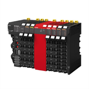
Omron NX-Series Safety Network Controller
NX Series CIP Safety Controller with EtherCAT and Ethernet/IP capabilities. In addition to new hardware, Sysmac Studio new functions include Automatic Programming, Safety Data Logging, and Online Functional Test. For more information visit: USA Canada Mexico
03:16
Omron NX-Series Safety Network Controller
NX Series CIP Safety Controller with EtherCAT and Ethernet/IP capabilities. In addition to new hardware, Sysmac Studio new functions include Automatic Programming, Safety Data Logging, and Online Functional Test. For more information visit: USA Canada MexicoRelated products
-
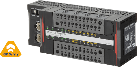
GI-S Series
-
Modular IP20 IOs
-
From single machine to production line all, safety interconnect
-
Integrated safety into machine automation
Downloads